My first experiences of frame building involved some sort of jig. 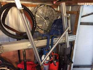 The was some angle iron bolted to a sheet of MDF (for my tandem BMX and recumbent) and then a proper jig at Downland Cycles for their framebuilding course.
To starting to make frames at home I thought I needed a jig. Looking at the retail options was a bit of a financial shock. Lovely though they were, they were all well into 4 figures which seemed a bit steep. How hard can it be?
Marc Andre Chimonas, lugged frame construction manual uses a couple of pieces of angle iron and a vice, which is a fine start but I wanted to try fillet brazing so wouldn’t work as well!
After quite a lot of internet and book (remember them?) research there seemed to be a fair number made out of extruded aluminium. This comes in various forms and is used to make various structures from production lines to marketing stands.
RS components do a number of types as well as various mountings. I chose one I thought was about the right size and had mountings that fitted my design.
The design was basically one large, horizontal central boom and two ‘uprights’ to mount the seat tube and head tube on. It then has an extension sticking out which is adjustable horizontally and vertically to hold the rear dropouts.
The main concern with this design was to ensure the uprights stayed parallel and upright. I chose about as large a central boom as I could to help that and always try to ensure I keep an eye on the angle of the uprights.
The other main design I saw was more of a rectangle with the two uprights connected across it. Like this:
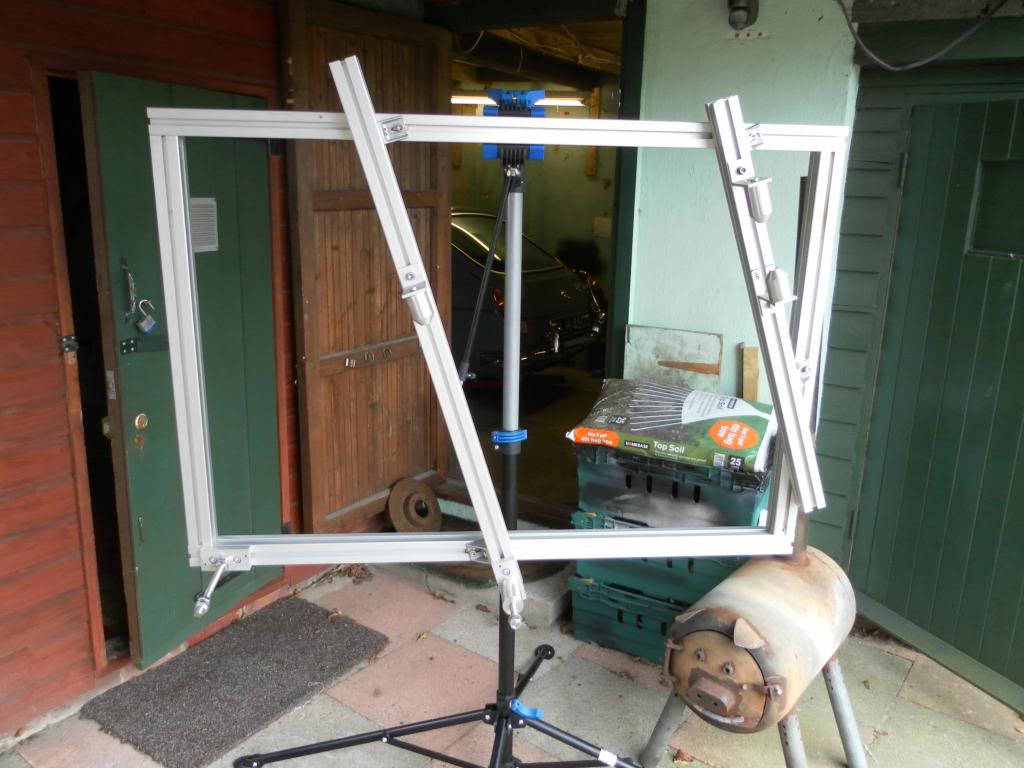
These generally look pretty sturdy. They do take more material (cost more) and are generally physically larger (my space is at a premium). I chose the first option on the basis that if it didn’t work I could always change it to be like the one above.
Next job was to connect all the bits together and make the mounts to hold the frame. All the connecting bits together should be available from the same supplier as the beams. I wanted large sturdy mounts to hold everything rigid and straight. The ones I choose also had an ‘L’ shaped mount I could use to hold the tube holding cones in. Using the measurement of those I made up the other various mounts to make sure the centre line was all the same distance from the jig.
One thing to think about is where you are going to be brazing from and how much space you need. The other advantage of the central boom is you have pretty good access around the frame.
Next bits were the dropout mounts. I made up a few dummy axles out of 15mm steel (different lengths 120, 130, 135) and put some bolt holes in the end so I could screw in some 8mm bolts to hold the dropouts tight. To mount that I needed some way of holding that dummy axle and being able to bolt that to and adjust it on the jig. The simplest idea seemed like a block of aluminium with some holes bored through it for the clamping bolts and axle..
In hindsight I could have just used some threaded bar through the block rather than making a dummy axle but it seemed like a good idea at the time. I preferred the idea of something that was the right width to bolt up to rather than have nuts either side of the dropout which could move and upset the alignment more easily. Total cost was around £5-600. It could be done for less but at least the decimal point was in the right place.
Next thing to think about was angles and measurements. To set the seat and head angles I use a bevel box angle finder like this one:
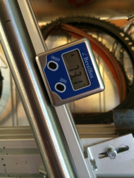
It’s nearly my most favourite tool ever. So easy to use. If the jig boom is flat then it’s a piece of cake to get uprights at the angle you want. It’s also magnetic so stays where you put it.
It has to be said that with cones to hold tubes and this box, it is easy to setup the frame up so it is not straight. Never has the phrase measure twice, braze once been such an understatement.
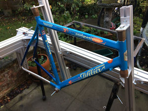
To set the measurements of where the tubes should be, for the first frame I cheated. I was building a frame to a known dimension, close to that of a frame I had. I set the jig up with that frame in it and then adjusted from there. I have since put some markings on the jig to help and will eventually get round to attaching some rulers to it, hopefully.
The next step was to try and use it! The main question in my mind was how well the frame would stay straight in or out of the jig when being brazed. I decided to do most of the brazing in the jig and see if it held it straight.
I ended up welding pretty much all of it in the jig, including brazing upside down, which isn’t advisable or easy. It did end up with a frame that was pretty straight though.
The main problem was caused by lighting. In situ I can only get to one side of the jig. There’s a fair amount of leaning over, through and round to complete the joints. Most of the lighting comes from the door of the shed being open (as well as some lighting in side. As this is off to the side it makes things look straight when they’re not and vice versa. Measure twice!
To help some of that, I made a stand so I could move the jig outside when the weather would play ball. In the end I’ve moved more towards doing less brazing in the jig and not having to move it anywhere. To be able to rotate it on its horizontal axis would be handy but near impossible in the space I have.
The other thing to consider if building a jig is what size bike you want to be able to use it for. I made mine able to handle bikes much bigger than my 5’11” needs, with bottom brackets of 68mm, 73mm and 100mm, super long chainstays, just in case. Some of that causes more faff than it sometimes seems sensible but when I get to building a snow bike for someone who’s 6’5” the payoff will have been worth it.